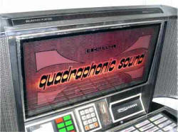
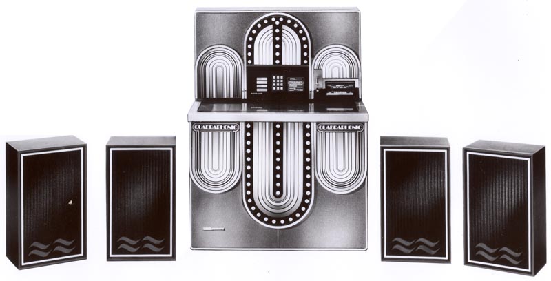
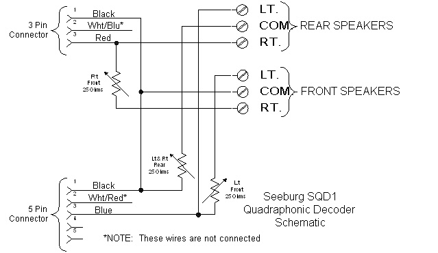
The SQS160 was the first version of the Seeburg Quadraphonic system available from the factory. There were two differences between the SQS160 (at left) and the STD160. The first is the upper graphic panel, as you can see. The second was the inclusion of the type SQD1 Seeburg Quadraphonic Encoder inside. It plugged directly into the cabinet cabling, replacing the connections to the bass speakers in the cabinet base, and the crossover network and tweeter connections, which are part of the installed SN12 Stereo Network.
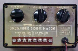
 The SQD1 is a small box,approximately four inches
(10 cm) wide by 6 inches (15 cm) long by 1 1/2
inches (4 cm) high. This box contained three
adjus
The SQD1 is a small box,approximately four inches
(10 cm) wide by 6 inches (15 cm) long by 1 1/2
inches (4 cm) high. This box contained three
adjus
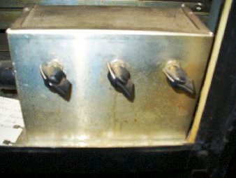
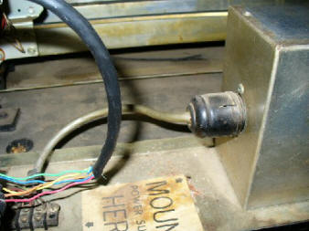
 This is a photo of the inside of the decoder,
showing the three wire-wound potentiometers
and the wiring. The original of this photo can
also be found on the website listed above. An
unadvertised modification made to the factory
built units was to have the choke mounted on
the preamplifier board disconnected at one end.
This choke serves to make the amplifier monaural
at low frequencies, an attempt to minimize audio
feedback into the amplifier. Since the console
speakers were disabled as part of the installation,
the choke was no longer needed. Chances are
this modification was actually performed on
very few of the factory-supplied units.
This is a photo of the inside of the decoder,
showing the three wire-wound potentiometers
and the wiring. The original of this photo can
also be found on the website listed above. An
unadvertised modification made to the factory
built units was to have the choke mounted on
the preamplifier board disconnected at one end.
This choke serves to make the amplifier monaural
at low frequencies, an attempt to minimize audio
feedback into the amplifier. Since the console
speakers were disabled as part of the installation,
the choke was no longer needed. Chances are
this modification was actually performed on
very few of the factory-supplied units.


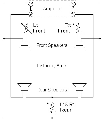
This is how it's connected to the speakers. Note that the 'Lt Front' and 'Rt Front' potentiometers are connected in series with the front or main speakers. They simply serve to control the relative volume between the front and rear speakers. The rear speakers are connected across both amplifier output channels, with the 'Lt & Rt Rear' control connected between the common connections of the rear speakers and the amplifier common output terminal. Connected in this manner, the Rear speakers will only output the difference between the Left and Right amplifier outputs. The 'Lt & Rt Rear' potentiometer controls how much of this 'difference' signal you hear. With it set to 0 Ohms, all you hear is the amplifier Left and Right audio. With the control set for maximum resistance, you get the maximum effect. This simple circuit was invented by David Hafler (U.S. Patent #3,697,692), and was licensed to the Dynaco Corporation by him. In fact, he was the founder of Dynaco and one of the main designers of most of their amplifiers, renowned in the 50s, 60s, and 70s for superb high-end audio systems. This simple circuit recovers the rear ambient sounds such as audience coughs or applause, which the recording microphones generally pick up in opposite phase to what is generated by the musicians. Also picked up are echoes from the recording location. All this adds to the ambience or realistic sound of many recordings. The effect will vary from record to record, but the operators simply set the controls so that the average record sounded okay, and left it at that. I'm not sure you would hear much difference in the typical place where you would find the jukebox. It seems to me you would have to listen in a pretty quiet environment to pick up any rear channel sounds. Home installations would certainly sound much better than the typical bar or restaurant.
class="F4 Bold FontArial Black"